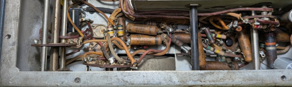
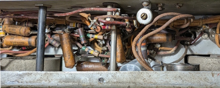
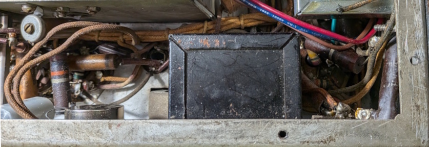
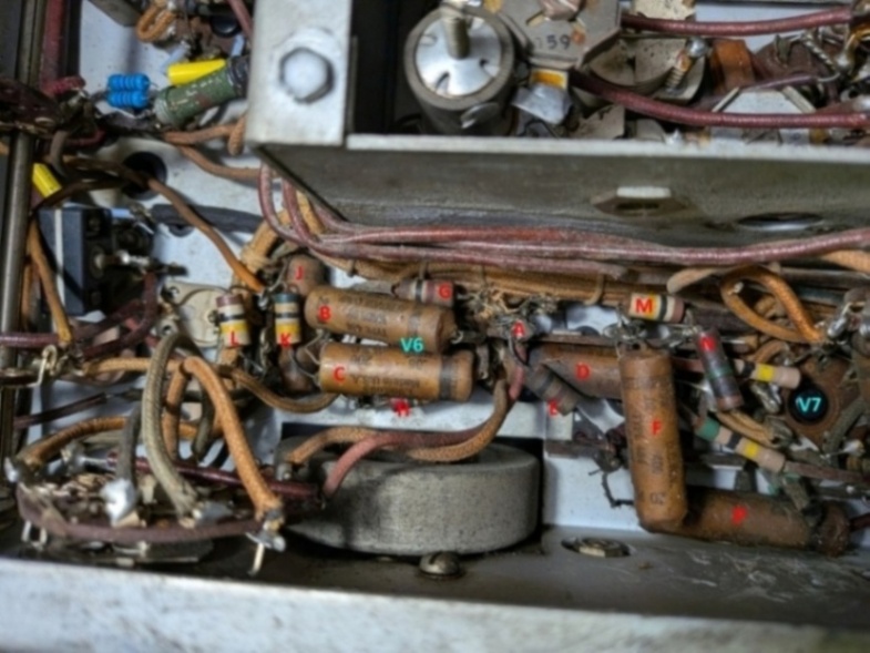
The circuitry just behind the front wall of the chassis
On close examination, I find this. What in the world happened here?
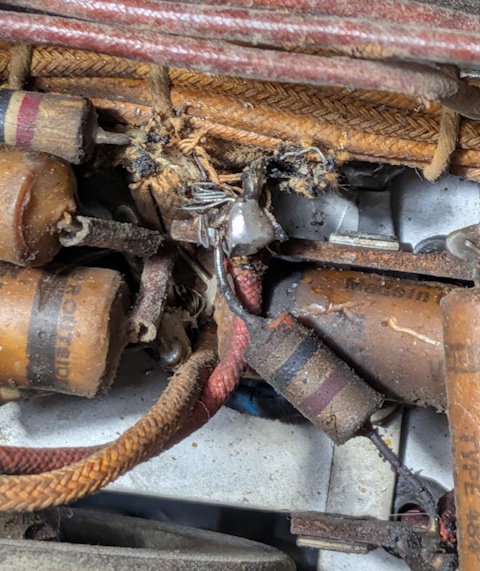
I removed the plastic rod used for the antenna trim.
Decided the first thing to do is ID parts:
T3 wire colors on this radio appear to be red, green, blue and black. (Pretty sure it's black.)
Red goes to junction of R23 and C36 (B+ supply to V6 plate).
Blue goes to V6 pin 8 (plate).
Green goes to V7 pins 4 and 5 (and the gimmick capacitor).
Black must go to junction of C37 (47 pf), R24 (100K ohm), and R70 (1M).
Noticed this. Is it a smoking gun?
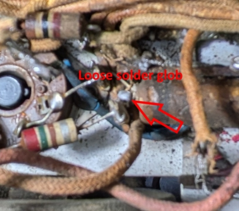
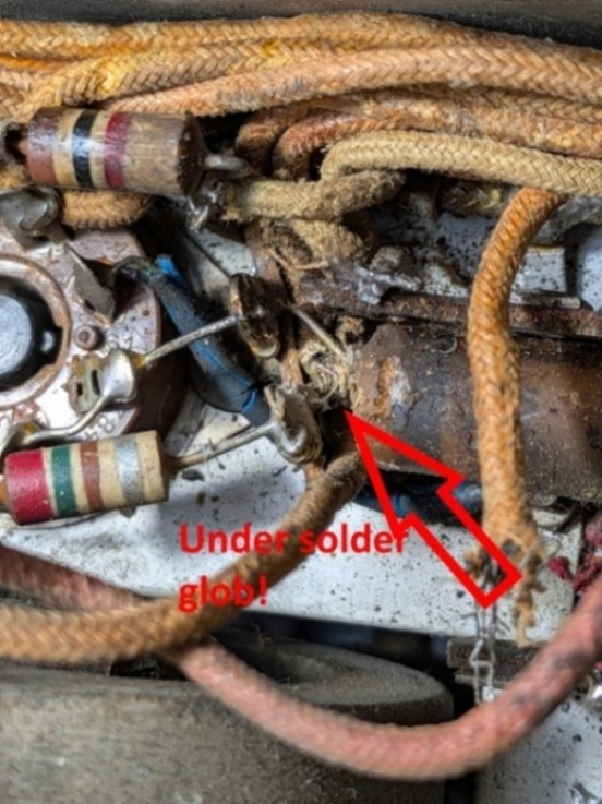
As noted on the progress picture page, the wires from the transformer are in horrible shape. There is no real alternative to removing T3 and rewiring it. Will give a good opportunity to compare against other T3 transformers and update the transformer resistance tables.
I ran into a lot of difficulties trying to reinstall the rewired transformer. See Reinstall Woes. Also this. Might want to skip all of it if you have something useful to do. It's extremely tedious.
Current working schematic:
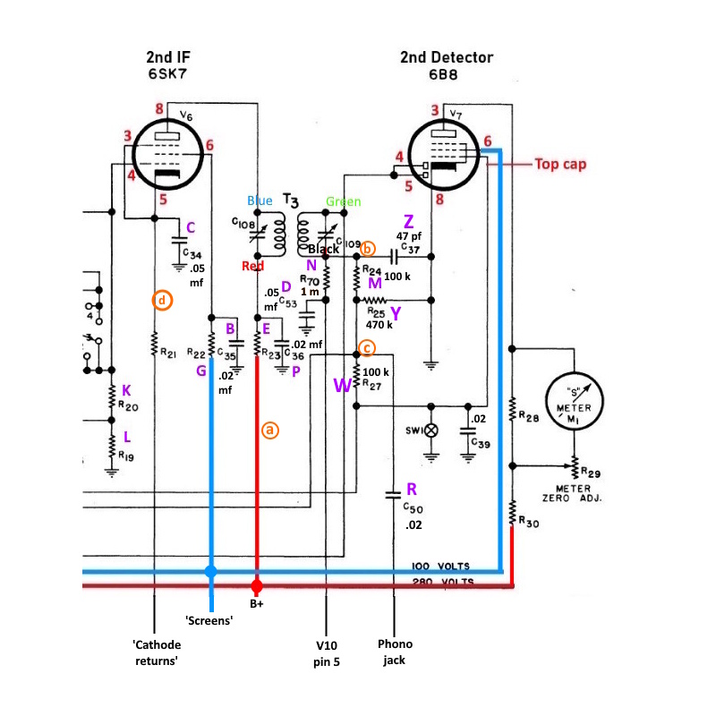
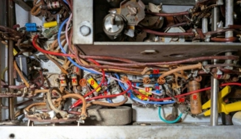
Almost complete. I've added some 'nodes' in orange circles. They appear on the schematic above and the photo below.
The red and blue wires are B+ and screens respectively.
The radio had an antique 500K resistor at W (R27, shown disconnected below) that measured about 750K. The latest parts list gives R27 as 100K so changed to that value.
Page: /5th_radio_resurrection/Recap_1/Recap_V6_V7.shtml
Last modified: Thursday, 23 Apr 2026