Transformer resistance tables for T1
The examples of this part that I examined all seemed to have different wire colors. When I
rewired them, I used my own colors. I used the same colors for each one I rewired.
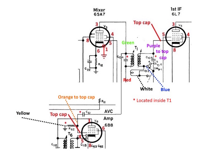
The schematic snippit shows the interior parts of T1 with an '*' symbol and the 7 wires
coming out of the can with my selected wire colors.
C104 and C105 are across the primary and secondary windings and located on the interior circuit board.
C51 and R62 are also inside the can. They are shown in the lower part of the schematic snippet. The 'wire'
drawn between the two parts of the schematic is inside the can.
Radio #1
            Purple - white: 7.11 ohm
            Brown - white: 0.34 ohm
            Yellow - orange: 466,000 ohm (onboard resistor)
            Green - red: 6.8 ohm
            Brown - purple: 6.8 ohm
Radio #2
Note the difference between the Green - red reading here vs the other examples. I have no explanation for it.
            Purple - white: 7.25 ohm
            Brown - white: 0.33 ohm
            Yellow - orange: 466,000 ohm (onboard resistor)
            Green - red: 11.76 ohm
            Brown - purple: 6.94 ohm
Radio #3
            Purple - white: 7.32 ohm
            Brown - white: 0.33 ohm
            Yellow - orange: 473,000 ohm (onboard resistor)
            Green - red: 6.98 ohm
            Brown - purple: 7.01 ohm
Radio #4
Radio #4 is an early version. Perhaps this explains the dramatically different value for the resistor R62.
            Purple - white: 7.03 ohm
            Brown - white: 0.38 ohm
            Yellow - orange: 960,000 ohm (onboard resistor)
            Green - red: 6.69 ohm
            Brown - purple: 6.66 ohm
Radio #5
This transformer was never removed from the radio.
Page: /T1/Resis_tbl.shtml
Last modified: Friday, 24 Apr 2026