Oscillator Module Switch Wafers
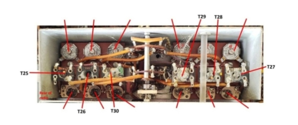
The oscillator module has three wafers: 8, 9 and 10 counting from the rear of the radio.
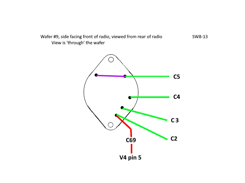
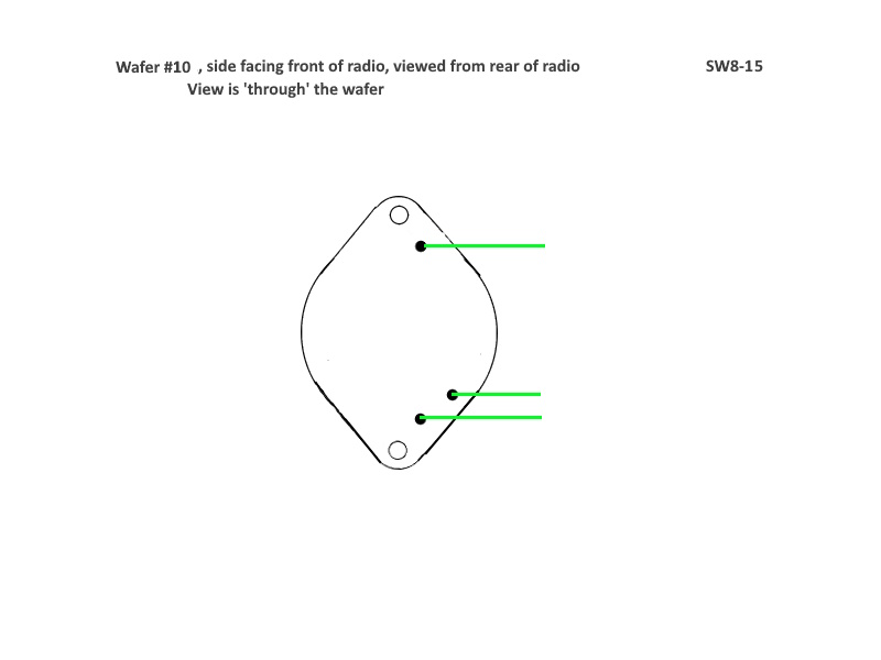
On the schematic, these switches are labeled SW8-11, SW8-12/13, SW8-14 and SW8-15 respectively.
There are some significant differences between my schematic and the oscillator
transformers. My schematic shows six 3-wire transformers. The hardware has T27 and T30 (bands 3 and 6) as
4-wire transformers
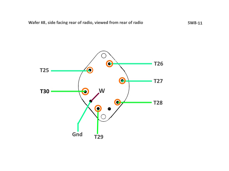
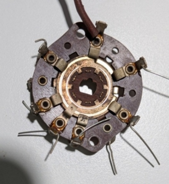
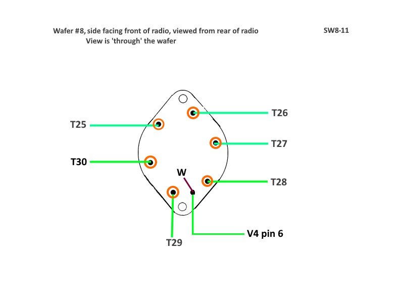
Beware of different viewpoints. One is 'through', the other is face on.
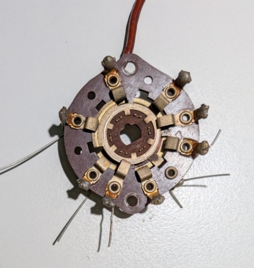
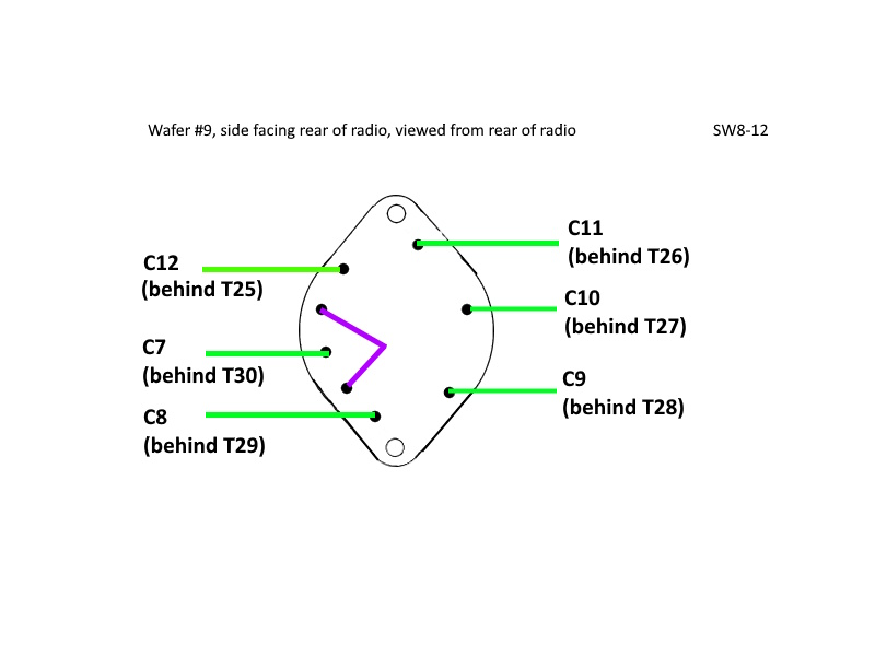
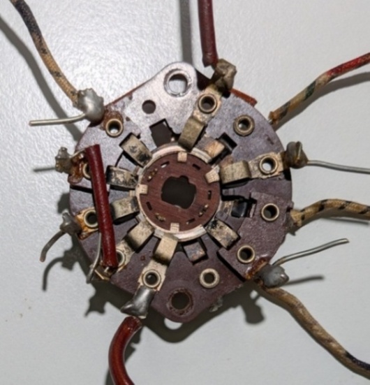
The SW8-13 pin that is shown connecting to C69 is, according to the schematic, also supposed to connect to C13 (to ground) and SW8-12.
Need to figure out how that works.
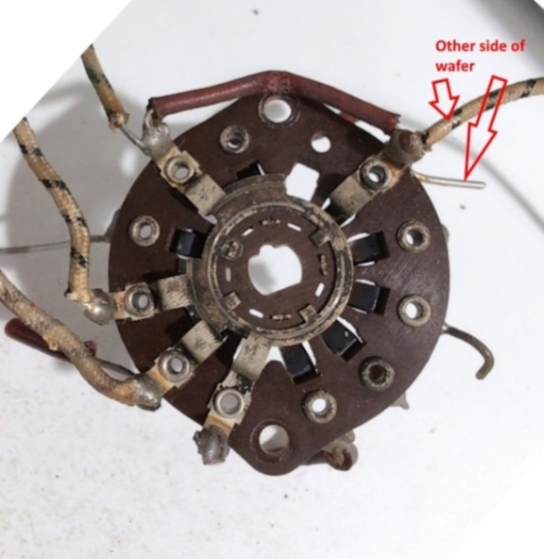
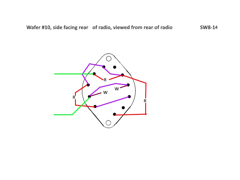
SW8-14 has it's very own schematic symbol that doesn't match anything else! It has something to do with the 'cathode returns'
and switching resistors in and out to the cathode of V5 in the 1st IF stage.
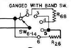
Beware of different viewpoints. One is 'through', the other is face on.
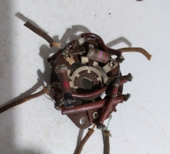
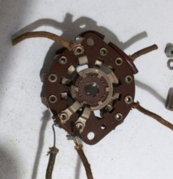
On an early radio (s/n H_118969), there does not appear to be an SW8-15. There are no contacts on
the side of the wafer facing the oscillator module chassis.
Beware of different viewpoints. One is 'through', the other is face on.
Page: /Band_switch/Late/Osc_switch_wafers/Osc_switch_wafers.shtml
Last modified: Saturday, 9 May 2026