Adjustment of the Oscillator
Equipment Requirements for Oscillator Adjusting
- Scope. The scope trace is not suitable for frequency measurements
- Frequency counter
- Non-metalic screw driver
Common Instructions For All Bands
The radio must be upside down with the front panel facing you for this test. I found it easier to work
with if it was on its side, power transformer down1.
Important: Set the bandspread tuning to 100 on the 0-100 scale.
It might be possible2 to connect a scope probe to one end of the mica capacitor going from V4 pin 6 to V3 pin 5.
It might be possible to connect a scope probe to V3 pin 5.
Either will work.
Suggest AC input setting.
Band One
-
Switch the band switch to band one. Tune main dial to exactly 1,400 KHz
- Observe a sine wave on the scope with a period of 0.54 ㎲ and 1,855 KHz on the counter
- Amplitude should be about 3 V p-p
- Adjust C98 for for proper frequency
-
Tune main dial to exactly 600 KHz
- Observe a sine wave on the scope with a period of 0.95 ㎲ and 1,055 KHz on the counter
- Adjust T25 for for proper frequency. You may need to adjust C12 to get T25 in the middle of its range
- Yeah, that's one of those "Don't mess with this" things
-
Return to the lower frequency and verify things are still correct.
Band Two
-
Switch the band switch to band two. Tune main dial to exactly 2,800 KHz
- Observe a sine wave on the scope with a period of 0.31 ㎲ and 3,255 KHz on the counter
- Amplitude should be about 3 V p-p
- Adjust C99 for for proper frequency
-
Tune main dial to exactly 1,600 KHz.
- Observe a sine wave on the scope with a period of 0.48 ㎲ and 2,055 KHz on the counter
- Adjust T26 for for proper frequency. You may need to adjust C11 to get T26 in the middle of its range
-
Return to the lower frequency and verify things are still correct
Band Three
-
Switch the band switch to band three. Tune main dial to exactly 5,600 KHz
- Observe a sine wave on the scope with a period of 0.17 ㎲ and 6,055 KHz on the counter
- Amplitude should be about 3 V p-p
- Adjust C100 for for proper frequency
-
Tune main dial to exactly 3,200 MHz.
- Observe a sine wave on the scope with a period of 0.27 ㎲ and 3,655 KHz on the counter
- Adjust T27 for for proper frequency. You may need to adjust C10 to get T27 in the middle of its range
-
Return to the lower frequency and verify things are still correct
Band Four
-
Switch the band switch to band four. Tune main dial to exactly 11,000 KHz
-
Observe a sine wave on the scope with a period of 0.087 ㎲ or 11,455 KHz on the counter.
Amplitude should be about 3 V p-p.
Adjust C101 for for proper frequency.
-
Tune main dial to 6,000 KHz.
-
Observe a sine wave on the scope with a period of 0.015 ㎲ or 6,455 KHz on the counter.
Adjust T28 for for proper frequency. You may need to adjust C9 to get T28 in the middle of its range.
Band Five
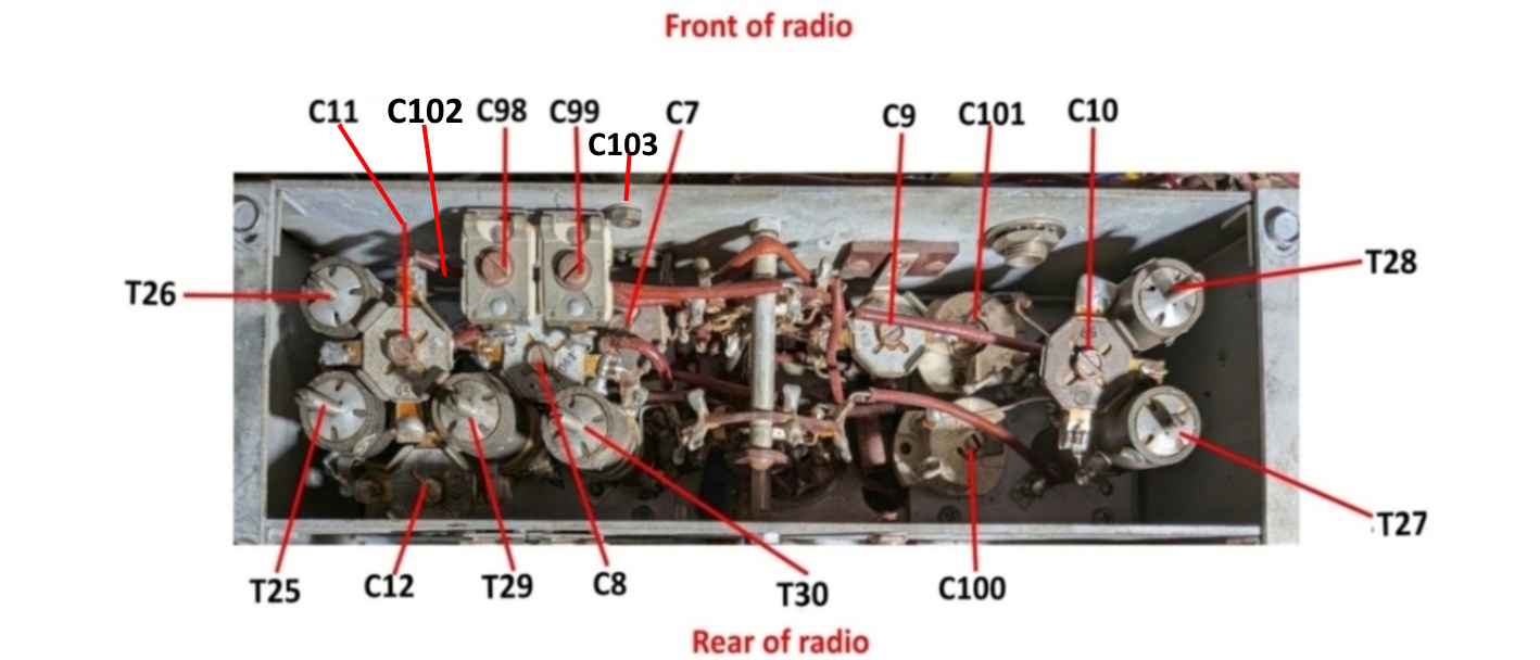
The adjustment capacitor C102 for band five is a normal air variable located under C98. Strongly suggest a
sturdy plastic alignment tool for this one.
-
Switch the band switch to band five. Tune main dial to 20,000 KHz
-
Observe a sine wave on the scope with a period of 0.049 ㎲ or 20,455 KHz on the counter.
Amplitude should be about 3 V p-p.
Adjust C102 for for proper frequency.
-
Tune main dial to 11,000 KHz.
-
Observe a sine wave on the scope with a period of 0.087 ㎲ or 11,455 KHz on the counter.
Adjust T29 for for proper frequency. You may need to adjust C8 to get T29 in the middle of its range.
Band Six
The adjustment capacitor C103 for band six is this funny looking tube thing with a screw on one end. It is either inside the oscillator chassis
just under C99 or on the outside just opposite C99.
-
Switch the band switch to band six. Tune main dial to exactly 36,000 KHz
- Observe a sine wave on the scope with a period of 0.027 ㎲ or 36,455 KHz on the counter
- Amplitude should be about 3 V p-p
- Adjust C103 for for proper frequency
-
Tune main dial to 22,000 KHz.
- Observe a sine wave on the scope with a period of 0.044 ㎲ or 22,455 KHz on the counter
- Adjust T30 for for proper frequency. You may need to adjust C7 to get T30 in the middle of its range
-
Return to the lower frequency and verify things are still correct
Footnotes:
-
Power transformer down for lower center of gravity, less chance of falling over and ruining your entire day.
-
On the two radios I had available, one connection was made to the mixer end of the
cap (the insulation sleeve was a little short) and on the other, connection was made to V3.
Page: /Alignment/Osc/Adjust/Align_early_osc_adjust.shtml
Last modified: Monday, 22 Jun 2026