While messing with the alignment procedures and trying to get some adjustments to stay put, I discovered that the measurement equipment I was using was having as much of an effect on the radio as the radio was having on the measuring equipment. Even scope probes were skewing oscillator frequencies.
After consulting with Gemini AI, a plan was hatched to build an active probe. This page documents the probe but not the AI. It was a convoluted discussion full of errors and false starts. If you're interested in having such a discussion, start your own. The initial prompts are not very involved.
Amazon has active scope probes. They start at $300 and go to $2,000 or more. Most of them seem to be related to high voltage, not microscopic signal loading.
So... Welcome to Redneck RadioShack
Image shamelessly stolen from Google Images
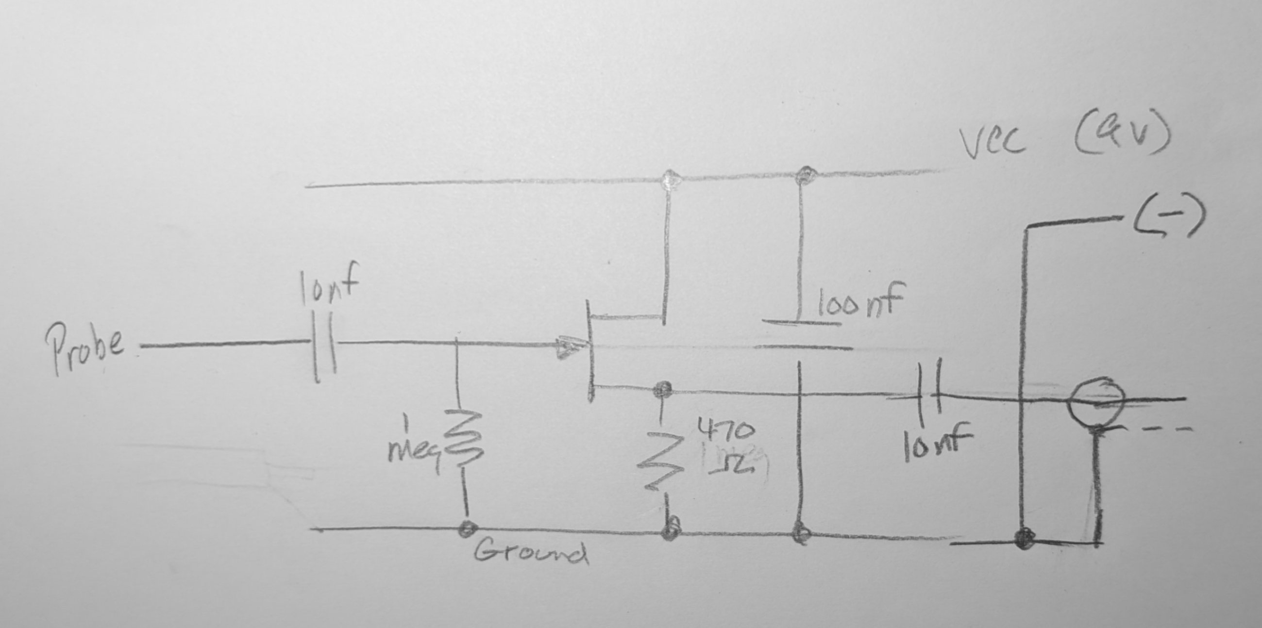
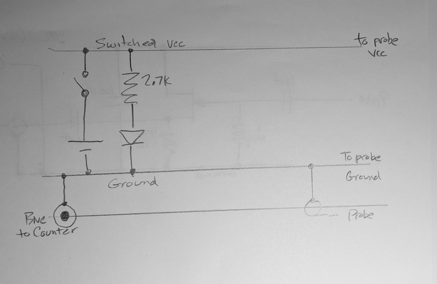
Our probe will have two parts: the 'little board' and the 'big board'. The little board goes in the radio and connects to some point. There is a cable to the big board which hangs out near the scope or counter and connects via a standard 50 ohm patch cable.
The bill of materials:
The circuit for each board was determined using the Gemini AI system (Google). Mickey suggested the two-part construction and Gemini suggested the use of the JFET J310 and the use of co-ax. Mickey initally rejected the co-ax due to the cost of a entire spool to acquire 2 feet of wire. Mickey also noted that he did not have any J310 parts. The design then went to using a 2N2222 and twisted pair with an investigation into using a piece of light-weight Ethhernet cable (4 pairs twisted). A small quanity of co-ax was discovered on Amazon so the design immediatly went back to that. J310 parts were also discoverd at a very reasonable rate.
Once the various parts were decided, Gemini designed the circuit. As noted below, it's a very modest circuit.
Since Gemini is not able to draw a schematic and efforts to locate some program whereby Gemini could provide a text file (node list) for input and subsequent printing were not successful, a scheme was devised with Gemini giving a word description and Mickey drawing the circuit with a pencil and paper. The result was uploaded to Gemini for verification. 1st attempts were successful for each board. The uploaded images:
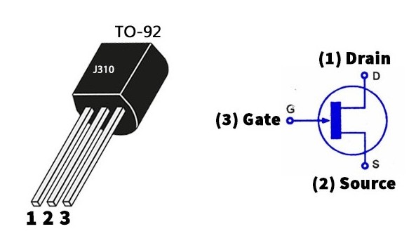
J310 pinout:
1st progress picture below. Mickey sent this to Gemini and got approval. Don't
misinterpret 'approval'. If there was something stupid, Gemini is
smart enough to point it out.
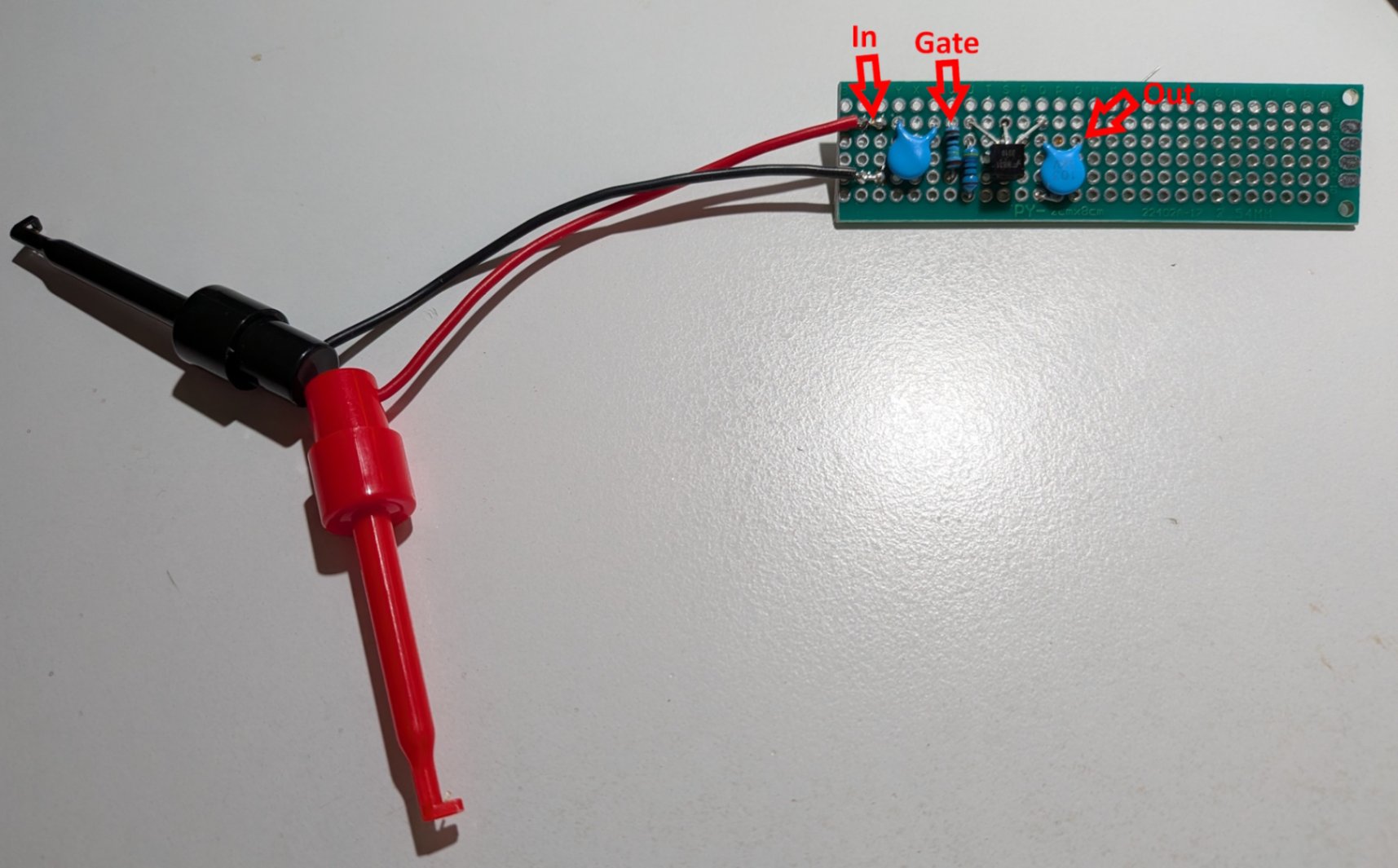
REST PENDING ARRIVAL OF COAX WIRE...
Page: /Active_probe/Active_probe.shtml
Last modified: Friday, 31 Jul 2026